Engineering Graphics — ES 101 — is the course where you learn that a drawing is not a picture. It is a contract. Whatever you do not dimension does not exist, and whoever has to make the part gets to interpret your silence however they like.
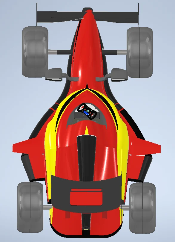
Our cohort was split into groups of ten and told to model something real. Group 11 picked a Formula One car, using a Mercedes W05 cutaway as the reference for proportions. Twenty-eight components between us, modelled in Autodesk Inventor, each one needing a full drawing sheet before it was allowed near the assembly.
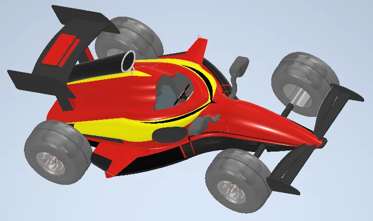
The two parts that were mine
I want to be precise about this, because "I modelled a Formula One car" would be a lie. I modelled two of the twenty-eight components. Both drawing sheets carry my name in the title block, dated 07-07-2023.
The first was the middle chassis, with the side air ducts and cockpit display. It is the part that sets the car's waist: the survival cell the driver sits in, the ducts that feed air down the flanks, and the little display panel on the steering column.
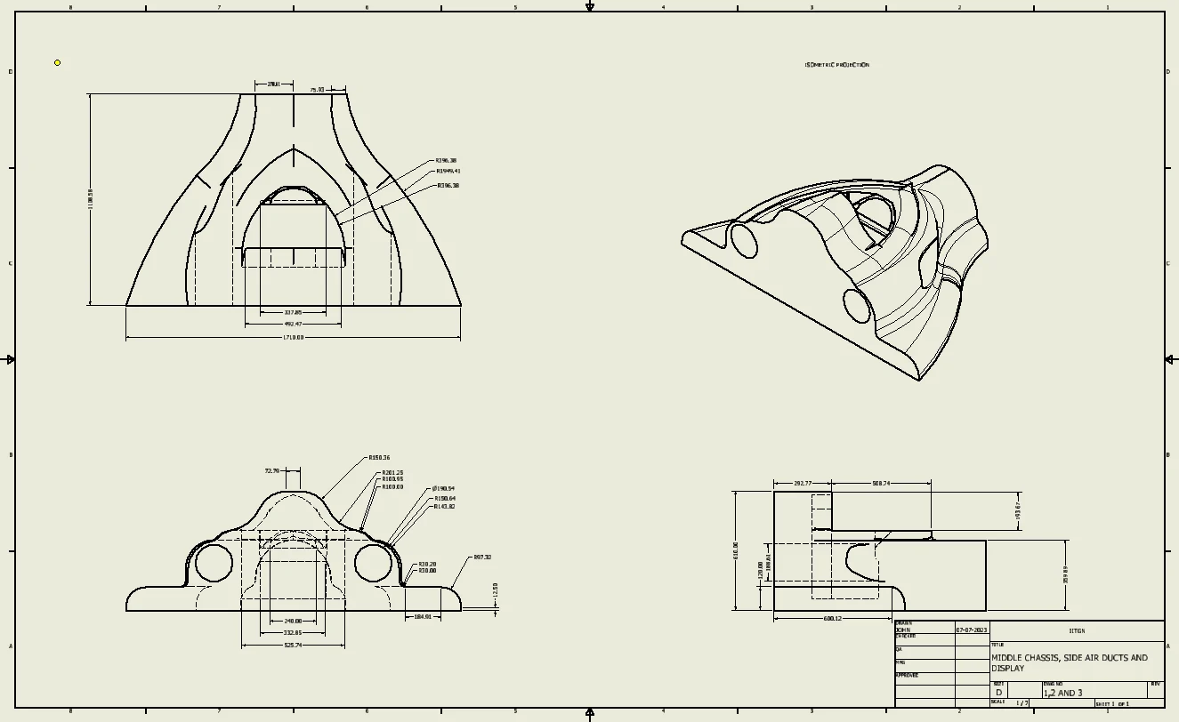
Almost none of that part is straight. The front elevation is a stack of tangent arcs — R196.38 into R1949.41 into R306.38 — and each one has to be called out individually, because a radius you do not specify is a radius someone else will guess. The overall width is 1710.00 across the base and 692.47 across the cockpit opening. Numbers to two decimal places on a shape I had drawn freehand a week earlier felt absurd until I tried to assemble it against someone else's part and the two faces did not meet.
The second was the control pedal, drawn at 4:1 because at 1:1 you cannot see anything useful.
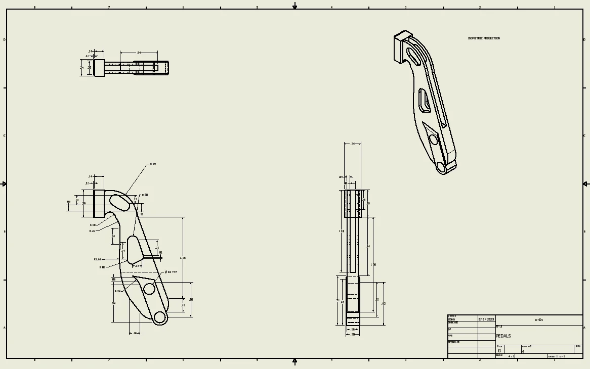
A pedal is a deceptively annoying object. It is mostly a lever with two lightening cut-outs, but the pivot boss, the pad angle and the cut-outs all have to be located relative to each other, and the part is small enough that the dimension lines take up more room than the geometry does.
What the sheet demands
Every component in the report follows the same discipline, and it is a discipline worth naming:
- Orthographic views — front, top, side. Enough of them, and only enough, to describe the part without ambiguity.
- An isometric projection, because orthographic views are precise and completely unreadable to anyone who has not been trained on them.
- Dimensions that fully constrain the geometry. Not most of it. All of it.
- A title block — part name, scale, sheet number, who drew it, when.
That last one seemed like bureaucracy in first year. It is the reason I can tell you three years later exactly which two parts were mine.
Assembly is where the lying stops
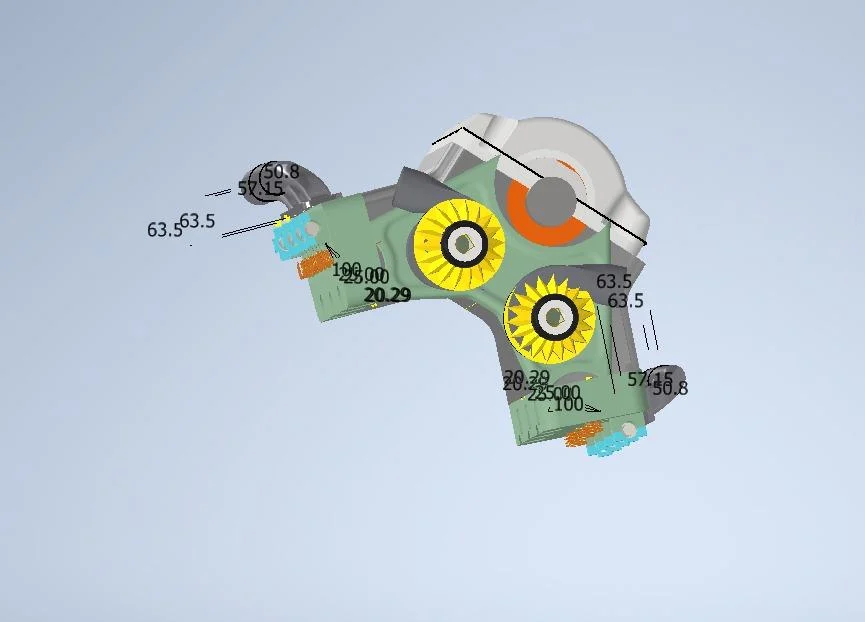
The constraint I had not appreciated was that ten people modelling independently will produce parts that do not fit, and the assembly is where you find out. Mating faces that were "about right" in isolation are visibly wrong once constrained against a neighbour. Our rear chassis went through at least five saved revisions; you can still see them in the project folder as rear__chassis__finallll and friends, which is its own kind of documentation.
Why I still think about it
I have not opened Inventor in a while. What carried over was not the tool.
It was the habit of asking what a description leaves unspecified. A drawing sheet punishes vagueness immediately and visibly — the part comes back wrong, or it will not mate. Most of what I work on now is software, where the same vagueness hides for much longer: an interface that does not say what happens on a retry, a function whose behaviour at the boundary was never written down. The feedback is slower, but the failure is the same one.
Twenty-eight parts, ten people, and the parts fit. That only happened because everybody dimensioned everything.
ES 101 Engineering Graphics, IIT Gandhinagar. A group project by Group 11 — ten students. My contribution was the middle chassis with side air ducts and cockpit display, and the control pedal; the other twenty-six components were my teammates' work. The reference cutaway we worked from is Paolo D'Alessio's illustration of the Mercedes F1 W05, which is not reproduced here.